ODU
ODU
Introduction
Table 1-1 Performance attributes of the ODU
Item
|
XMC-1 ODU
|
XMC-2 ODU
|
|---|---|---|
ODU type
|
Low capacity for ODU
|
ODU in high power
|
Frequency band
|
7 GHz, 8 GHz, 11 GHz, 13 GHz, 15 GHz, 18 GHz, and 23 GHz
|
6 GHz, 7 GHz, 8 GHz, 10GHz, 11 GHz, 13 GHz, 15 GHz, 18 GHz, 23 GHz, 26 GHz, 28 GHz, 32 GHz, 38 GHz, and 42 GHz
|
Microwave modulation format
|
QPSK and 16QAM
|
QPSK, QPSKSTRONG, 16QAM, 16QAMSTRONG, 32QAM, 64QAM, 128QAM, 256QAM, 512QAM, 512QAMLIGHT, 1024QAM, 1024QAMLIGHT
|
Channel spacing
|
3.5 MHz, 7 MHz, 14 MHz, and 28 MHz
|
3.5 MHz,7 MHz, 14 MHz, 28 MHz, 40 MHz, and 56 MHz
NOTE:
|
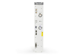
Table 1-2 Appearance description of the ODU
Serial No.
|
Item
|
Description
|
|---|---|---|
1
|
Guide pin
|
The guide pin is used together with the guide trough to facilitate the installation of the ODU.
|
2
|
Polarization direction identifier
|
H: Horizontal polarization
V: Vertical polarization
|
3
|
Cooling fins
|
The 45°slant angle of the cooling fins ensures the ventilation of the ODU in horizontal-polarized and vertical-polarized conditions to facilitate heat dissipation.
|
4
|
Handle
|
The handle is used to facilitate the holding and installation of the ODU.
|
5
|
Pressure vent
|
Ensures that the pressure inside the ODU and that outside the ODU are the same, thus preventing explosion. In addition, the pressure vent valve can prevent moisture.
|
6
|
RSSI interface
| |
7
|
IF interface
| |
8
|
Grounding screw
| |
9
|
Cut corner
|
In horizontal and vertical conditions, cables are inclined from the cut corner to enhance waterproof reliability.
|
Functions
The ODU, a microwave RF unit, has the function of frequency conversion and power amplification. The ODU determines microwave frequencies of the transmitted and received signals and is not affected by transmission service types such as the TDM Serivce and Ethernet service.
The ODU supports the following features:
- Various channel spacing.
- Various modulation formats.
- Adaptive modulation (AM) function.
- Adjustment of TX/RX frequencies through software.
- Adjustment of TX power through software.
- Temperature detection.
- TX power detection.
- RX power detection.
- Received Signal Strength Indicator (RSSI) interface:The ODU has an RSSI interface, which indicates the RX power in voltage.
- Mute transmission.
- Automatic Transmit Power Control (ATPC).
- Remote Transmission Power Control (RTPC).
- Automatic Gain Control (AGC) function of received signals:The ODU automatically adjusts the channel gain according to the level of received signals.
Figure 1-3 Direct mounting mode
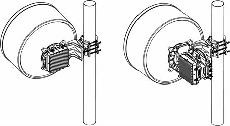
Figure 1-4 Separate mounting mode using a single-polarized antenna
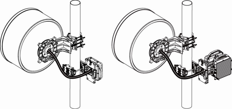 Figure 1-5 Separate mounting mode using a dual-polarized antenna
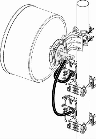
Figure 1-6 Interfaces of the ODU
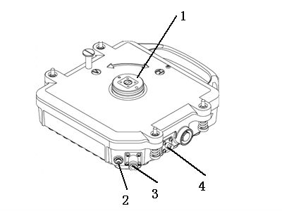 Table 1-3 Interfaces of the ODUSerial No.Interface NameInterface TypeDescription1Antenna interface153IEC-R70, can be interconnected with the PDR70 (6 GHz frequency band)153IEC-R84, can be interconnected with the PBR84 (7/8 GHz frequency band)153IEC-R100, can be interconnected with the PBR100 (10G/11 GHz frequency band)153IEC-R120, can be interconnected with the PBR120 (13 GHz frequency band)153IEC-R140, can be interconnected with the PBR140 (15 GHz frequency band)153IEC-R220, can be interconnected with the PBR220 (18/23/26 GHz frequency band)153IEC-R320, can be interconnected with the PBR320 (28/32/38 GHz frequency band)UG 383/U-R400, can be interconnected with the UG 383/U-R400 (42 GHz frequency band)The antenna interface is a waveguide interface that is connected to an antenna, a hybrid coupler, an antenna adapter, or a flexible waveguide.2Grounding screwM5 screwThe grounding screw is connected to the PGND cable.3IF interfaceN type (female)The IF interface is connected to the IDU through an IF cable.4RSSI interfaceBNC type (female)The received signal strength of the ODU can be calculated based on the voltage of the interface that is measured through a multimeter.

Explained deeply thanks for sharing
ReplyDeleteFlexible waveguide